Why Is My Light Flickering? (And What to Do About It)

Your light is flickering. Before you call an electrician, an exorcist, or your landlord — here’s what it actually means and how to fix it yourself.

It flickers. You look at it. It stops. You go back to what you were doing. It flickers again.

Your brain, being your brain, immediately skips past ‘probably just the bulb’ and lands directly on ‘the house is haunted’ or ‘I need to re-wire everything and possibly move.’

Here’s the good news: flickering lights usually mean something pretty simple. The bad news is that occasionally — only occasionally — they do mean something worth paying attention to.

The key is knowing which situation you’re in. Let’s figure it out.

The Basic Principle: Flickering = Interrupted Power

A flickering light means power is getting interrupted to the bulb — something is breaking the circuit briefly, then reconnecting. Think of it as the electrical equivalent of a bad handshake.

That ‘something’ is usually one of four things:

  • A loose connection
  • A failing component
  • A power demand issue
  • The bulb itself being dramatic

The pattern of the flickering tells you which problem you’ve got. Pay attention to it.

Pattern #1: One Light, Flickers Occasionally

Single light. Flickers now and then. Sometimes a few times in a row, sometimes hours go by between episodes. Classic.

Start Here: Replace the Bulb

We know. It seems too simple. Replace it anyway. Old bulbs lose contact with the socket. LED bulbs can throw a fit in fixtures with certain dimmer switches. Incandescent bulbs at end-of-life like to go out dramatically, flickering their way to the grave like a character in a Victorian novel.

Turn off the light, swap in a new bulb (same type and wattage), and watch it for a few days. That’s it.

Cost: $2–20. Solution rate: embarrassingly high.

If the New Bulb Doesn’t Help: Check the Fixture

The bulb socket can loosen over time, creating an intermittent connection. Corrosion or dust in the socket can do the same thing. In fluorescent fixtures, the ballast — the component that regulates power — can start to fail, causing flickering before it gives up entirely.

For a loose or dirty socket: turn off the power, gently clean it with a dry brush, reinstall the bulb. For a failing ballast: fixture replacement is usually cheaper than repair and less aggravating than explaining what a ballast is to your spouse.

Cost: $0–150, depending on what you find.

Pattern #2: Multiple Lights Flicker at the Same Time

Several lights in different rooms, all flickering together. Happens when you fire up the oven, the AC kicks on, or the dryer starts its cycle.

Most Likely Cause: Voltage Drop

When high-draw appliances start up, they pull a lot of electricity at once. This temporary surge in demand causes a brief voltage dip across the whole house. Lights are sensitive to voltage — they notice.

A brief flicker when a big appliance kicks on is completely normal. Your electrical system is just responding to the demand. If the lights merely blink and recover, go back to your sandwich.

It becomes worth calling someone if:

  • The flickering is severe or the lights dim noticeably
  • It’s getting worse over time
  • It happens even without major appliances running

Those symptoms could mean an undersized electrical service, a loose connection at the main panel, or a utility company issue out at the street — none of which you’re going to fix with a screwdriver.

Cost: $0 if it’s normal behavior. $100–500+ if there’s an actual loose connection at the panel.

Pattern #3: One Light Flickers Constantly

Steady, rapid, continuous flickering. It doesn’t stop. It’s annoying. It might be making you slightly unhinged.

Check the Dimmer Switch First

Modern LED bulbs and old dimmer switches do not always get along. Older dimmers were designed for incandescent bulbs, which draw more power and work differently. Put an LED on that dimmer and it gets confused, which it expresses through flickering.

Test it: set the dimmer to full brightness. If the flickering stops, you’ve found your culprit. Your options are to replace the dimmer with an LED-compatible one ($15–40) or swap in a dimmable LED bulb rated for your specific dimmer ($5–15). Either fix works.

If It’s Not the Dimmer: Loose Connection

Constant flickering with no dimmer involved usually means a loose connection somewhere — in the fixture itself or at the wall switch. Turn off power at the breaker, check the connections, tighten anything that’s loose.

If you’re not comfortable poking around in electrical boxes, this is when you call someone. No shame in that.

Cost: $0–200, depending on where the loose connection lives.

Pattern #4: Flickering Gets Worse Over Time

Started minor, keeps getting worse. The light is heading toward not working at all — it’s just taking its time getting there.

This pattern almost always means internal component failure. It’s not dangerous, but it’s not going to fix itself. Replace the fixture before it dies completely and leaves you standing in the dark, annoyed.

Cost: $50–150 for a new fixture and installation.

When to Actually Call an Electrician

Most flickering is harmless. But some of it isn’t, and here’s how to know the difference:

  • Flickering is accompanied by a burning smell or sparks — stop, turn off power, call immediately
  • Multiple circuits are affected and it’s not appliance-related
  • You suspect a loose connection at the main panel
  • Constant flickering persists after you’ve tried new bulbs and dimmer swaps
  • You’re just not comfortable messing with electrical connections — a completely legitimate reason

An electrician visit runs $100–200 for diagnosis, $200–500+ if there’s actual work to do. That’s not cheap. It’s also not a house fire. Keep that in perspective.

The Quick Diagnostic Flowchart

One light flickers occasionally → Replace the bulb. Probably done.

Multiple lights flicker together → Likely voltage drop from an appliance starting. Normal.

One light flickers constantly → Check the dimmer. If there is one, get a compatible bulb or switch. If there isn’t, loose connection — call an electrician.

Flickering is getting worse → Component failure. Replace the fixture.

Burning smell or sparks → Turn off the circuit. Call an electrician. Do not read the rest of this article.

The Bottom Line

Flickering lights are annoying. They are rarely catastrophic. Most of the time it’s the bulb. Sometimes it’s the fixture. Occasionally it’s just your house doing normal house things when the dryer kicks on.

Try the easy fixes first. New bulb, check the dimmer, note whether multiple lights are doing it together. You’ll solve most flickering problems before you’ve had to look up a single phone number.

And if the house turns out to be haunted — well, that’s a different post.

Related Guides You Might Find Helpful

Amazon Affiliate Recommendations

Bulbs & Replacements

LED Bulbs (Dimmable) – If you have dimmer switches, dimmable LEDs are your friends. Quality matters here — avoid the cheapest options or you’ll be back in this article in three months.

LED Bulbs (Non-Dimmable) – For standard fixtures without dimmers. More affordable, and flicker-free as long as your dimmer switch isn’t the issue.

Dimmer Switches & Fixtures

LED-Compatible Dimmer Switch – If your dimmer is the problem, replacement is straightforward and solves it permanently.

Light Fixture Replacement Kits – When a fixture keeps flickering after bulb replacement, sometimes the cleanest answer is a new fixture.

Testing & Diagnosis

Voltage Tester (Non-Contact) – Confirms whether a circuit is live before you work on it. Use this every single time.

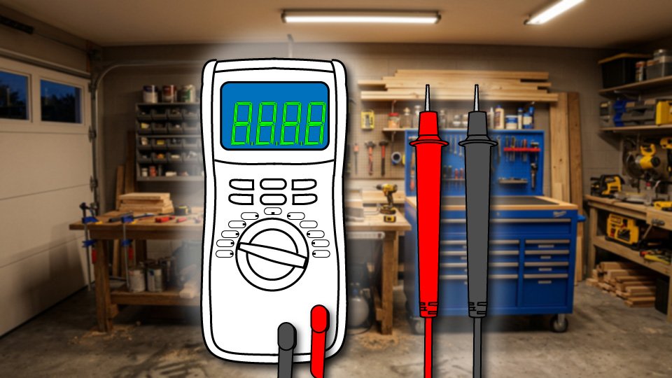
Multimeter – For more detailed electrical diagnosis if you want to check voltage or continuity yourself.

As an Amazon Associate, I earn from qualifying purchases. Click through the links above to support Skippity Whistles.


Electrical work involves risk. Always turn off power at the breaker before working with fixtures or switches. If you smell burning or see sparks, turn off the circuit immediately and call a licensed electrician.


Skippity Whistles is part of the John D Reinhart content family. Writer, illustrator, videographer, and accidental filmmaker — find the whole story at JohnDReinhart.com.

9019

©2026 John D Reinhart/SkippityWhistles.com – All rights reserved

Why Your Circuit Breaker Keeps Tripping (Or: Stop Flipping It and Start Listening)

A breaker that keeps tripping isn’t broken — it’s shouting. Here’s what it’s actually trying to tell you, and when to stop flipping it back on.

Ron ran his toaster, his microwave, and his coffee maker at the same time every single morning, and every single morning the kitchen breaker tripped somewhere around minute two. His fix was consistent: walk to the panel, flip it back on, walk back to the kitchen, repeat tomorrow. He’d been doing this for months. The breaker had been trying to tell him something the entire time, and Ron had been answering by hitting snooze.

A breaker that trips repeatedly isn’t malfunctioning. It’s doing exactly the job it was built for — and ignoring that message by simply flipping it back on, over and over, is how a minor annoyance turns into a genuine hazard.

⚡ The Core Principle: It’s a Hero, Not a Villain

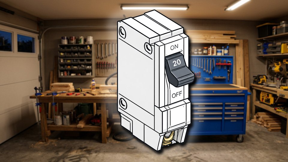
A circuit breaker watches the current flowing through its circuit, and if that current exceeds the breaker’s rating, it trips and cuts power immediately. Too much current generates heat; too much heat melts wire insulation; melted insulation is how house fires start. A tripping breaker isn’t the problem. It’s the thing standing between a problem and a much worse outcome.

🔥 The Five Reasons a Breaker Actually Trips

  • Overloading the circuit is the most common cause, and it’s exactly what caught Ron every morning. A 120-volt, 20-amp circuit tops out around 2,400 watts — Ron’s toaster (1,200W), microwave (1,000W), and coffee maker (1,000W) running together add up to 3,200 watts, well past what the circuit can carry. This is a spread-the-load problem, not a broken-breaker problem.
  • A short circuit happens when the hot and neutral wires touch directly instead of routing current through whatever’s plugged in — often from damaged internal wiring in an appliance — and trips the breaker instantly and forcefully.
  • A ground fault occurs when current escapes to ground through an unintended path, commonly water or moisture near an outlet.
  • Faulty wiring — old, damaged, or loosely connected — creates resistance, and resistance generates heat that eventually trips the breaker even without an obvious overload.
  • And, rarely, the breaker itself is simply wearing out and tripping without any real fault behind it at all.

🔍 Diagnosing It Yourself

Don’t just keep flipping it back on — that’s answering a warning by muting it, not solving it.

Note what was actually running the moment it tripped; that alone often points straight at the answer.

Unplug everything on that circuit, then reset the breaker:

  • If it holds with nothing plugged in, the problem is overload, not a wiring fault.
  • If it trips again with nothing plugged in at all, that’s a deeper problem — short circuit, ground fault, or faulty wiring — and not something to keep testing alone.

Once it holds, reintroduce devices one at a time until the culprit reveals itself.

🚫 What Never to Do

  • Never replace a breaker with a higher-amp one to make the tripping stop — the wiring behind it is only rated for the original amperage, and a bigger breaker just means the wiring overheats before anything trips to stop it.
  • Never wedge a coin or any object behind a breaker to hold it on — this has genuinely happened, more than once, and it completely defeats the one thing standing between an overload and a fire.
  • Never treat occasional trips as fine just because they’re infrequent; infrequent is still a warning.
  • And never route a high-draw appliance through an extension cord to another circuit as a workaround — that doesn’t solve the overload, it just relocates it somewhere with its own limits.

📞 When to Call an Electrician

  • A breaker that trips with absolutely nothing plugged in
  • A breaker that trips consistently at a specific outlet
  • A breaker that had been tied to a specific appliance and continues to trip even after the appliance is confirmed faulty
  • or any hint of a burning smell or scorch marks near the panel

All of these are past the point of DIY troubleshooting. That’s not a failure to solve it yourself. It’s recognizing exactly where the line sits.

🛒 Gear Worth Having

Klein Tools NCVT-3 Non-Contact Voltage Tester — Confirms what’s actually live before any hands-on diagnosis starts — the same first step worth taking every time.

Basic Digital Multimeter — Measures voltage and current directly, which turns a guessing game about an overloaded circuit into an actual number.

Heavy-Duty Surge Protector Power Strip — Rated for real appliance loads, not the flimsy strip that turns three high-draw devices into one overloaded outlet.

As an Amazon affiliate, I earn from qualifying purchases. Thank you for supporting SkippityWhistles.

📖 Related Reads

SkippityWhistles is part of the John D Reinhart content family. Writer, illustrator, videographer, and accidental filmmaker — find the whole story at JohnDReinhart.com.

9020

©2026 John D Reinhart/SkippityWhistles.com — All rights reserved
How to Read an Electrical Panel: Your House’s Electrical Nervous System Explained

Intimidated by your breaker box? Here’s what every homeowner should know: what those switches do, why your house has them, and when to call an electrician—explained in plain English.

Ron’s breaker labels were mostly guesswork — half of them read “???” from a previous owner who clearly gave up at the same point Ron eventually would. His method for finding the right breaker during any given problem was flipping switches one at a time and waiting to hear which room went quiet. It worked, eventually, the way hitting every button in an elevator eventually gets you to your floor. It’s just not what anyone would call reading the panel.

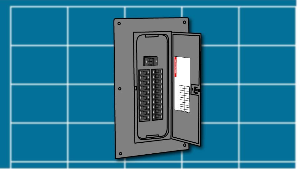
An electrical panel looks like a wall of identical switches guarding a mystery, but it’s really just a traffic cop — deciding how much power goes where, and giving you a way to shut any of it off. Once you know what you’re actually looking at, the guessing stops.

🚦 The Main Disconnect: The Big Switch

Near the top of most panels sits one larger breaker, usually labeled MAIN, with its own amperage rating printed on it — 100, 150, or 200 amps in most homes. This is the main disconnect, and it cuts power to the entire house at once. In some homes, especially older or larger ones, the main disconnect sits outside the panel entirely — worth knowing where yours actually is before an emergency makes that knowledge urgent.

🔌 Breakers: Single-Pole and Double-Pole

Below the main sit columns of smaller breakers, each protecting one circuit — a single circuit might feed several outlets or lights, but they all answer to the same breaker. A single-pole breaker (narrow, one switch) handles standard 120-volt circuits — most of the outlets and lights in a house. A double-pole breaker (wider, looks like two switches joined together) handles 240-volt circuits — the water heater, central air, an electric range, a dryer, anything genuinely power-hungry enough to need double the voltage.

🔗 The Neutral and Ground Buses

Along the sides of the panel sit two metal bars with wires clustered onto them. The neutral bus (usually silver or gray, with white wires attached) completes the circuit, carrying current back out. The ground bus (usually green or bare copper) provides a safety path for electricity if something goes wrong elsewhere in the circuit. Neither is a random cluster of wires — both are doing specific, structural work every time anything in the house draws power.

🏷️ Reading the Labels

A properly labeled panel tells you exactly what each breaker controls and how much current it allows — “Kitchen 20A,” “Bedrooms 15A,” “Water Heater 30A.” If the labels in a panel are faded, vague, or missing entirely, that’s genuinely worth fixing: flip one breaker at a time, note what goes dark, and write it down. Thirty minutes now saves a lot of Ron’s elevator-button guessing later.

🎨 What Breaker Colors Actually Mean

Color signals the type of protection, not how strong the breaker is — a red breaker isn’t more powerful than a black one, it’s just wired for a different voltage.

Black breakers are standard single-pole, 120-volt. Red breakers are standard double-pole, 240-volt. Yellow often indicates AFCI (arc fault) protection. Blue or green often indicates GFCI (ground fault) protection or a specialty breaker type.

Tandem or “twin” breakers — two thin breakers sharing one slot — show up in some panels and not others, since not every panel is rated to accept them. If a panel already has some, that’s useful to recognize when reading it — but whether more can safely be added is a question for whoever’s actually working inside that panel, not something to figure out by inspection alone.

⚡ Amperage: What the Numbers Actually Mean

The number stamped on each breaker — 15, 20, 30, 40 — is the maximum current that circuit is rated to carry before the breaker trips.

  • 15A handles light-duty circuits like bedroom outlets and lighting.
  • 20A is the general-purpose standard for kitchens and bathrooms.
  • 30A and up covers heavy-duty appliances like water heaters and dryers.

🏠 Service Size: How Much Power the House Has

The number on the main breaker is the house’s total service size — its overall electrical capacity.

  • 100A service is common in older homes and can feel tight running AC, a water heater, and an oven at once.
  • 150A covers a modest modern home reasonably, though it can get crowded with an EV charger or heat pump added later.
  • 200A is the standard for most homes built or renovated recently, and handles the typical mix of major appliances comfortably.

Anything beyond that is generally reserved for larger homes or all-electric construction.

🔄 What a Tripped Breaker Actually Means

A tripped breaker did its job — it caught an overload, a short, or a ground fault before that fault became something worse.

Unplug what’s on that circuit, flip the breaker fully off and back on, then reintroduce devices one at a time to find the culprit.

A breaker that trips immediately, every time, points to a real fault, not a coincidence — that’s an electrician’s call.

A breaker that won’t stay reset at all is a genuine red flag, not something to keep pressing and hoping.

🛡️ The Golden Rule: Look, Don’t Touch

Understanding a panel and working inside one are two completely different things.

Turning breakers on and off, testing GFCI and AFCI devices monthly, and keeping the panel clearly labeled and unobstructed are all reasonable homeowner territory.

Touching the main lugs or service entrance wires, sticking anything into the panel, or opening it up for repair work is not — those wires carry deadly voltage regardless of whether the main breaker is on or off, and that’s a licensed electrician’s job, every time, no exceptions.

🛒 Gear Worth Having

Klein Tools NCVT-3 Non-Contact Voltage Tester — Confirms what’s actually live near a panel before anything gets touched — a genuinely essential first step, not an optional one.

Label Maker for Breaker Panels — Turns a wall of guesswork into an actual reference, so the next person opening this panel doesn’t inherit Ron’s elevator-button method.

Circuit Breaker Finder and Outlet Mapper — Plugs into any outlet and identifies its breaker automatically, which turns labeling from an afternoon guessing game into a five-minute task.

As an Amazon affiliate, I earn from qualifying purchases. Thank you for supporting SkippityWhistles.

📖 Related Reads

SkippityWhistles is part of the John D Reinhart content family. Writer, illustrator, videographer, and accidental filmmaker — find the whole story at JohnDReinhart.com.

9015

©2026 John D Reinhart/SkippityWhistles.com — All rights reserved
GFCI & AFCI Outlets Explained

Those push-button outlets? GFCI and AFCI protect you from shock and fires. Here’s what they do, where you need them, and why they matter.

(Or: Those Buttons Are Not a Design Choice)

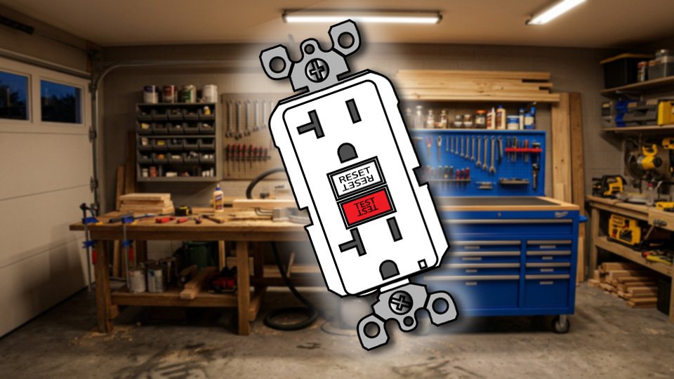
Ron plugged his phone charger into the bathroom outlet one morning and got nothing — no light, no charge, dead as a doornail. He unplugged it, checked the charger, tried a different outlet entirely, and was fully prepared to declare the whole bathroom electrically cursed before he noticed the small button in the middle of the outlet marked RESET. He pressed it. The outlet came back to life instantly, like it had just been waiting for someone to ask nicely.

Those push-button outlets in kitchens, bathrooms, and garages aren’t a style choice or a manufacturing quirk. They’re doing real, active work every second they’re plugged into the wall, and understanding what that work actually is makes the button a lot less mysterious.

⚡ The Problem These Outlets Solve

A regular circuit breaker protects your home’s wiring from overload, but it’s slow by design — it’s waiting for a large amount of current before it trips. If you’re standing in a puddle and touch a live wire or a faulty appliance, only a small amount of current needs to pass through you to cause real harm, and that small amount is nowhere near what it takes to trip a standard breaker. The breaker just isn’t built to catch that specific, smaller, more personal kind of danger.

🛡️ GFCI: The Fast Safety Cop

GFCI stands for Ground Fault Circuit Interrupter, and it works by constantly comparing the electricity going out on the hot wire to the electricity coming back on the neutral wire. When everything matches, nothing happens. When some current goes missing — because it’s escaping through you to the ground instead of coming back through the wire — the GFCI notices the mismatch and cuts power immediately.

A GFCI can detect a leak as small as 4 to 6 milliamps and cut power in about 25 milliseconds. For comparison, it takes roughly 100 milliseconds just to blink, and even longer for pain signals from your finger to reach your brain — meaning a GFCI can genuinely cut the power before you’ve even had time to feel the pain from an electric shock.

🔘 What the Buttons Actually Do

The TEST button intentionally creates a small fault to confirm the outlet’s safety mechanism is actually working — press it, and a functioning GFCI should trip immediately with an audible click. The RESET button restores power after a trip, whether that trip came from an actual fault or from testing. Test every GFCI outlet monthly; if pressing TEST doesn’t trip it, that outlet has failed and isn’t protecting anyone, and needs to be replaced.

📍 Where GFCI Protection Is Required

Building codes require GFCI protection specifically where water and electricity are most likely to meet at the same time you’re touching both — kitchen countertops, bathrooms, outdoor outlets, basements, garages, and laundry rooms. One GFCI outlet, installed first in line on a circuit, can protect every regular outlet downstream of it on that same circuit — which is why a kitchen might have just one or two GFCI outlets doing quiet duty for several ordinary-looking ones nearby.

🔥 AFCI: The Fire Prevention Cousin

AFCI stands for Arc Fault Circuit Interrupter, and it solves a different problem entirely. Where GFCI watches for current escaping to ground, AFCI watches for arcing — electricity jumping across a gap it shouldn’t be jumping across, caused by damaged insulation, a loose connection, or a worn cord. That spark runs hot enough to ignite nearby material inside a wall or an appliance, and AFCI protection is increasingly required in bedrooms, living areas, and throughout much of a modern home specifically to catch it before it starts a fire.

🤝 One Outlet, Both Protections

Combination GFCI/AFCI outlets exist and cover both hazards in a single device — pricier than either alone, but a genuine option for anyone updating outlets and wanting maximum coverage in one spot without installing two separate devices.

🔄 When One Trips

A tripped GFCI or AFCI outlet did exactly what it’s designed to do — it’s not broken, it caught something. Unplug whatever was connected when it tripped, then press RESET. If it trips again immediately, the fault is likely still present; if it stays on, plug devices back in one at a time to find the culprit. If it won’t stay reset at all, that’s a real problem with the outlet or the circuit, and it’s an electrician’s call, not a DIY one.

🧪 Testing Monthly Is Worth the Thirty Seconds

Plug in a lamp, turn it on, press TEST — the lamp should cut off immediately. Press RESET, and it should come back on. If TEST doesn’t trip the outlet, or it trips but won’t reset, that GFCI has failed and needs replacing. Thirty seconds a month is a small price for confirming a genuinely life-protecting device is still doing its job.

🛒 Gear Worth Having

GFCI Outlet Replacement Kit, Multi-Pack — Worth having a few on hand — most homes have more locations needing GFCI protection than people initially realize.

Combination GFCI/AFCI Outlet — Covers shock and fire protection in one device, for anyone updating outlets and wanting both bases covered at once.

Outlet Tester with GFCI Indicator — A cheap plug-in tool that confirms an outlet is wired and grounded correctly in seconds, no guesswork required.

As an Amazon affiliate, I earn from qualifying purchases. Thank you for supporting SkippityWhistles.

📖 Related Reads


SkippityWhistles is part of the John D Reinhart content family. Writer, illustrator, videographer, and accidental filmmaker — find the whole story at JohnDReinhart.com.

9014

©2026 John D Reinhart/SkippityWhistles.com — All rights reserved
How to Use a Voltage Tester (Or: How to Test a Wire Without Scaring Yourself to Death)

Before you touch a wire, one question matters: is this actually off? A non-contact voltage tester answers it in two seconds. Here’s how to use one correctly — including the step most people skip.

Before touching any wire, any outlet, any switch, or anything connected to your electrical system, one question needs an honest answer:

Is this actually off?

Not “I think I turned it off.” Not “I’m pretty sure that’s the right breaker.” Actually off, confirmed, zero voltage present. The only way to answer that question honestly is with a voltage tester — a tool that detects the presence of electricity before any hand goes anywhere near a wire.

The tool is simple, inexpensive, and one of the most important things in a home toolbox. Here’s how it works and how to use it correctly — including the one step most people skip but professional electricians never do.

🔌 What a Voltage Tester Does

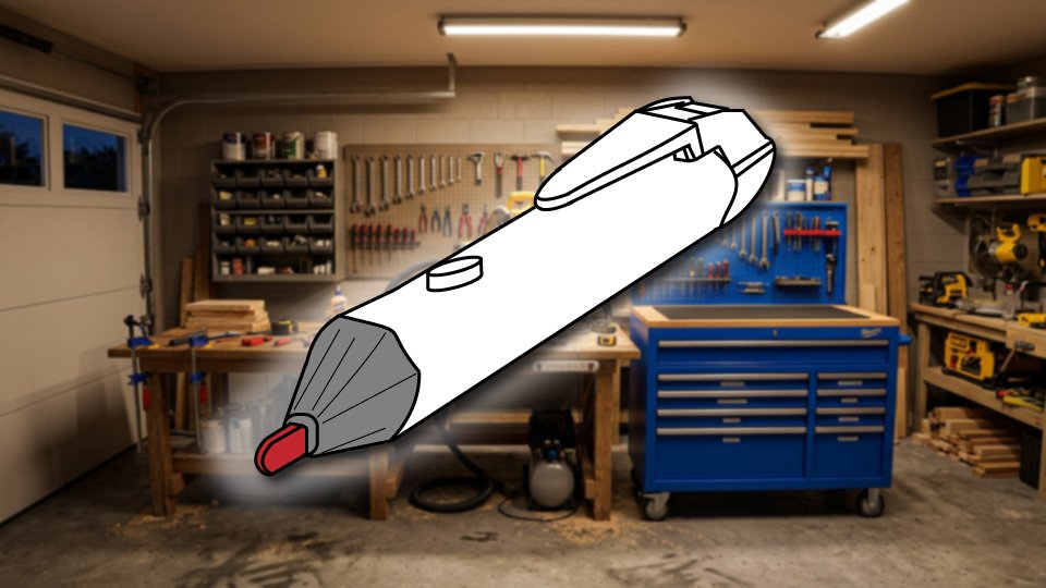
A non-contact voltage tester — also called an NCVT, a voltage pen, or a voltage detector — is a small, pen-shaped tool that detects the presence of electrical voltage without touching bare wires. You hold the tip near a wire, outlet slot, or electrical connection. If voltage is present, the tool beeps and the tip lights up red. If there’s no voltage, it stays silent and shows a steady green light.

That’s the entire function. It doesn’t measure how much voltage. It doesn’t diagnose wiring problems. It answers one question: is electricity present right here, right now? That single answer is what stands between safe electrical work and an extremely unpleasant experience.

The non-contact design is what makes it safe and practical for homeowners. Because the tip detects voltage through the wire’s insulation — the plastic coating around the wire — there’s no need to touch bare metal at all. Hold it near the wire, read the indicator, proceed accordingly.

🟢 Understanding the Lights

Every non-contact voltage tester has two indicator states, and knowing what each one means is the whole operating manual.

A steady green light means the tester is powered on and working. This is the standby state. Green means the tool is ready and has not detected voltage at the current location.

A flashing red light with an audible beep means voltage is detected. The circuit is live. Do not touch the wire. The beep and the red flash happen simultaneously, which means the tester communicates the warning even in a noisy environment where you might not hear the beep, or in a bright space where you might not notice the light change.

If the tester shows nothing at all — no green light, no response when you press the button — the batteries are dead or the tester has failed. This matters enormously, which is why the next section exists.

🔄 Live-Dead-Live Testing — The Step That Keeps Electricians Safe

Here is the procedure that professional electricians follow every time, and that most homeowners skip: Live-Dead-Live testing.

The concern is simple: what if the tester stopped working between when you last used it and right now? A tester with dead batteries shows no response on a live wire — which looks exactly like a dead wire. If you trust a silent tester without verifying it’s working, you’re trusting nothing.

Live-Dead-Live testing eliminates this risk in three steps.

First — Live: Before touching anything, test the tester on a known live circuit. A working outlet that you haven’t turned off is perfect. Hold the tip near the smaller slot (the “hot” slot — the one connected to the live side of the circuit) and confirm the tester beeps and flashes red. The tester is working.

Second — Dead: Go to the circuit you’re working on. Turn off the breaker at the electrical panel (the metal box with rows of switches, usually in a utility room, garage, or hallway — the breaker is the switch that controls the specific circuit). Now go back and hold the tester near the wire or outlet. No beep, steady green. The circuit appears to be off. Now go back to the circuit breaker and turn it on.

Third — Live again: Return to the known live outlet and test the tester once more. It beeps and flashes red. The tester is still working — which means the silent result in step two was accurate, not a dead battery.

This takes sixty additional seconds. It converts “I think the power is off” into “I have confirmed the power is off with a functioning tester.” That is not a small difference.

📋 Using It Step by Step

Turn on the tester and confirm the green light is showing. If there’s no light, replace the batteries before proceeding.

Take the steps above to verify that the tester is working correctly.

Go to the electrical panel and turn off the breaker controlling the circuit you’re working on. If the panel isn’t labeled — and many aren’t, fully or accurately — flip the switch for the room or fixture and confirm the light or device loses power before proceeding.

Hold the tester tip near the wire, outlet slot, or switch terminal you’ll be working on. Keep it close — within about half an inch of the surface. If it beeps and flashes red, the circuit is still live. The wrong breaker is off, or there are multiple circuits in the box. Find the right breaker before proceeding.

If the tester stays green and silent, go back and test on the known live outlet again. Confirmed still working. The circuit is off and the confirmation is real.

Proceed with the work.

⚠️ What a Voltage Tester Cannot Do

A non-contact voltage tester answers one question: is voltage present here? It cannot tell you how much voltage, whether the wiring is correct, whether the outlet is properly grounded, or whether the circuit has any other problems. Those questions require a multimeter — a more sophisticated tool that measures exact voltage values and tests continuity (whether a circuit is complete). Read about that here.

For basic homeowner electrical safety — confirming a circuit is off before working on it — the non-contact tester is the right and sufficient tool. For diagnosing electrical problems, understanding why an outlet isn’t working, or verifying proper wiring, a multimeter is the next step.

One additional note: never trust wire color alone. White wires are supposed to be neutral (not carrying current under normal conditions) and black wires are supposed to be hot (carrying current). “Supposed to be” does the heavy lifting in that sentence. Older homes, previous DIY work, and wiring errors mean wire color is not a reliable indicator of what’s live and what isn’t. Test every wire before touching it. Every time.

🛒 Gear Worth Having

Klein Tools NCVT-1P Non-Contact Voltage Tester — 50V to 1000V AC, Green/Red LED, Audible Alert — The tool that professional electricians and serious homeowners reach for. Green LED confirms it’s powered and working; red flash and audible beep when voltage is detected. Covers 50 to 1000V AC — the full range of residential wiring. CAT IV 1000V safety rating (the highest rating for general electrical work). Pocket clip, auto power-off to save batteries, compact enough to keep in any toolbox. Klein has been making professional electrical tools since 1857. This is the one.

Klein Tools NCVT1PKIT — Non-Contact Voltage Tester + GFCI Receptacle Tester, 2-Piece Kit — The NCVT-1P paired with Klein’s RT205 GFCI receptacle tester (the tool you plug directly into an outlet to check for wiring problems — open ground, reversed polarity, open hot, open neutral). The voltage tester tells you if power is present; the receptacle tester tells you if the outlet is wired correctly. Together they cover the two most common electrical safety checks a homeowner needs. The kit costs only slightly more than the tester alone.

Klein Tools NCVT-3P Dual Range Non-Contact Voltage Tester — 12-1000V AC, Built-in Flashlight — The upgraded option. Dual voltage range (12-1000V) means it also detects low-voltage wiring — doorbell systems, thermostat wiring, and landscape lighting that the NCVT-1P’s 50V minimum misses. The built-in flashlight illuminates junction boxes and outlet interiors where the work is happening. For anyone doing more than occasional electrical work, the dual range and flashlight are worth the modest additional cost.

As an Amazon affiliate, I earn from qualifying purchases. Thank you for supporting SkippityWhistles.

📖 Related Reads

How to Use Wire Nuts

How to Use a Voltmeter or Multimeter Safely

The DIYer’s Toolbox

Nervous people double-check things. That’s not a character flaw — it’s the right response to working near electricity. The voltage tester is what makes double-checking possible. Green light, silent tester, confirmed on a known live circuit immediately after: that’s not overcaution. That’s procedure. And procedure is what keeps the lights on — in the right sense of the phrase.


SkippityWhistles is part of the John D Reinhart content family. Writer, illustrator, videographer, and accidental filmmaker — find the whole story at JohnDReinhart.com.

9009

©2026 John D Reinhart/SkippityWhistles.com – all rights reserved

How to Use a Multimeter (Or: How to Actually See What Electricity Is Doing)

A multimeter tells you what electricity is doing — voltage, continuity, resistance — and removes the guesswork from DIY electrical work. Here’s how to use one without frying yourself or the meter.

Electricity is invisible. That’s both its charm and its fundamental problem — like dating someone who thinks they’re always in a movie scene. You can’t see it, you can’t smell it in normal quantities, and you can’t know what it’s doing without a tool that translates it into numbers you can read.

That tool is a multimeter — also called a digital multimeter, or DMM. If you’ve ever heard the word “voltmeter,” that’s the same thing, or close enough: a voltmeter measures voltage specifically, while a multimeter measures voltage and several other things besides. When you go to buy one, you’ll find multimeters on the shelf, not voltmeters. They do more and cost about the same.

Here’s what a multimeter measures, how to use it safely, and which one to buy first.

📊 What a Multimeter Actually Measures

The three measurements you’ll use most as a homeowner are voltage, continuity, and resistance.

Voltage is electrical pressure — the force that pushes current through a circuit. When you want to know whether an outlet is live, whether a wire is carrying current, or whether a battery still has charge, you’re measuring voltage. It’s measured in volts (V), and the reading tells you how much electrical pressure is present at that point in the circuit.

Continuity is whether a circuit is complete — whether electrical current can flow from one point to another without interruption. A continuity test tells you if a wire is broken, if a fuse has failed, or if a switch is making proper contact. Most multimeters signal a complete circuit with an audible beep, which means you can run the test without looking at the display. The beep means connected. Silence means broken.

Resistance is the opposition a material presents to the flow of electricity. Measured in ohms (Ω), resistance readings help diagnose component problems and verify that wiring is intact. For most homeowner electrical work, voltage and continuity cover the situations you’ll encounter. Resistance becomes relevant in more involved diagnostic work.

⚡ AC vs. DC — The Setting That Has to Match

Before taking any measurement, the multimeter dial needs to be set to the correct type of voltage. Getting this wrong produces either a meaningless reading or zero when there should be a number — which can be dangerous if it leads to the conclusion that power is off when it isn’t.

AC (Alternating Current) is what comes out of your wall outlets — the standard household current in the United States runs at approximately 120 volts AC. The dial marking is V~ (the tilde symbol indicates alternating). Use this setting for outlets, switches, light fixtures, and anything connected to household wiring.

DC (Direct Current) is what batteries produce, and also what solar panels, car electrical systems, and low-voltage electronics run on. The dial marking is V⎓ (the straight line indicates direct). Use this setting for batteries, car systems, and low-voltage DC applications.

Mixing up the settings — testing an AC outlet on the DC setting, or testing a battery on the AC setting — produces a reading of zero or a nonsensical number. If the reading doesn’t match expectations, the first thing to check is whether the dial is on the correct type of voltage.

🔌 How to Test an Outlet — Step by Step

Set the dial to AC Voltage (V~). We know that the voltage in most home AC circuits should be 120V. Click the dial on the multimeter until it points at 200V. Some meters feature auto-ranging, which chooses the range for you.

Connect the probes: black probe into the COM port (the port labeled COM, usually in the center or bottom), red probe into the VΩ port (the port for voltage and resistance measurements, usually labeled V or VΩ). Never put the red probe into the port labeled A — that port measures current (amperes), and connecting it across a voltage source will blow the meter’s internal fuse immediately. The A port is only used when measuring current, which requires a completely different connection method. Avoid the A port!

With the probes in the correct ports, insert the black probe tip into the wider outlet slot (the neutral slot) and the red probe tip into the narrower slot (the hot slot — the one connected to the live side of the circuit). Yes, into the slots.

A note on the finger-in-the-socket concern: this is a reasonable instinct that turns out not to apply to properly used test probes. The probe tips are insulated except at the very tip. Your fingers stay well behind the insulated guards. The meter has very high internal resistance that limits the current that flows through it to a level far below what’s dangerous. Electricians do this dozens of times a day. A properly used multimeter does not meaningfully increase shock risk compared to handling a normal lamp cord. Be brave – you can do this.

A live, properly wired outlet reads approximately 110 to 125 volts. Zero means the breaker is off or the outlet isn’t receiving power. A reading significantly different from the expected range suggests a wiring issue worth investigating.

🔋 How to Test a Battery

Set the dial to DC Voltage (V⎓). Choose a range slightly above the expected voltage of the battery being tested, or use auto-range.

Touch the red probe to the positive terminal of the battery (marked + on the battery) and the black probe to the negative terminal (marked −). The reading tells you the battery’s current voltage.

A good-condition AA battery reads approximately 1.5 volts. Below 1.2 volts and the battery is getting weak. A 9-volt battery reads 9 volts when fresh. A car battery reads approximately 12.6 volts when fully charged — below 12.4 suggests it’s getting tired, and below 12 volts means it’s significantly discharged and may struggle to start the car in cold weather.

Battery testing is one of the most immediately useful things a multimeter does. The difference between a dead battery and a weak battery is the difference between throwing away something that still has useful life and diagnosing a device problem correctly.

⚠️ The Rules That Protect the Meter and the Person Using It

Never change the dial setting while the probes are in contact with a live circuit. Set the dial first, then connect the probes.

Never use the continuity or resistance settings on a live circuit. Power off first, then test.

Never put the red probe in the A (current) port except when specifically measuring current — and measuring current requires breaking the circuit and connecting the meter in series, which is a different procedure entirely. The A port connected across a voltage source blows the fuse immediately.

Verify the meter is working before trusting a zero reading. A dead battery in the meter, or a blown internal fuse, shows zero on a live circuit. If a circuit that should be live reads zero, confirm the meter is functioning on a known live source before concluding the circuit is off. This is the same Live-Dead-Live principle covered in the voltage tester post — applied here to the multimeter.

🛒 Gear Worth Having

AstroAI Digital Multimeter 2000 Counts — AC/DC Voltage, Resistance, Continuity, Diode, Blue — The entry-level multimeter that handles everything a homeowner needs: AC and DC voltage, resistance, continuity with audible buzzer, and diode testing. Manual ranging with clearly labeled positions. Backlit LCD for working in dim spaces. Double-fused for overload protection. Over 73,000 Amazon reviews at 4.5 stars. This is the meter that earns its place in the toolbox on the first use and stays there for years.

AstroAI TRMS 4000-Count Auto-Ranging Multimeter — AC/DC Voltage, NCV, Battery Test, Flashlight — The step-up option. Auto-ranging means the meter selects the correct measurement range automatically — no dial sub-setting required beyond choosing the measurement type. TRMS (True RMS) measurement provides accurate readings on modern electronics and appliances that use non-standard waveforms. Built-in NCV (non-contact voltage detection) function, flashlight, and specific battery test modes for 1.5V, 9V, and 12V batteries. The right choice for anyone who wants the meter to do a little more thinking.

Klein Tools MM325 Digital Multimeter — 600V AC/DC, Manual Ranging, Backlit Display — Klein’s entry into the homeowner multimeter category, built to the same standards as their professional electrical tools. 600V AC/DC range, resistance to 2MΩ, continuity with buzzer, diode test, and battery test. Tough rubber housing that survives the toolbox. The brand that professional electricians trust in a meter priced for the homeowner who wants professional-grade reliability without the professional price tag.

As an Amazon affiliate, I earn from qualifying purchases. Thank you for supporting SkippityWhistles.

📖 Related Reads

How to Use a Voltage Tester

How to Use Wire Nuts

The DIYer’s Toolbox

A multimeter doesn’t fix anything. It tells the truth — whether power is present, whether a circuit is complete, whether a battery has enough charge left to be useful. In DIY electrical work, truth is the tool. Everything else follows from knowing what’s actually there.


SkippityWhistles is part of the John D Reinhart content family. Writer, illustrator, videographer, and accidental filmmaker — find the whole story at JohnDReinhart.com.

9012

©2026 John D Reinhart/SkippityWhistles.com – all rights reserved

How to Work with Electricity (Or: Respect the Breaker Panel)

You don’t need to be an electrician to work safely around your home’s wiring — just the habits that keep you that way.

Ron once explained to his neighbor that you can tell if a wire is live by tapping it quickly with the back of your hand — something about how a quick tap won’t let your muscles clench around the wire the way a full grip would. His neighbor, wisely, did not try this. Ron didn’t either, for the record. He just liked saying it with authority.

That’s the thing about electricity: everybody’s got a method, a trick, a thing their uncle swore by. None of it replaces the two habits that actually keep you safe. This post is about those two habits — and about understanding what’s actually happening behind your outlets and switches so “be careful” turns into something you can act on.

🔌 What’s Actually Behind the Wall

Every outlet and switch in your house connects back to a junction box (the plastic or metal box inside your wall where wires are joined together and protected) and, eventually, to your breaker panel (the metal box — usually in a basement, garage, or utility closet — where your home’s electrical circuits split off from the main power line, each protected by its own breaker).

Each circuit runs on wire rated by gauge (a number describing wire thickness — the lower the number, the thicker the wire, and the more current it can safely carry). A 14-gauge wire is standard for a 15-amp lighting circuit; a 12-gauge wire steps up to a 20-amp circuit, like the one your kitchen outlets are probably on.

Using a wire rated for less current than the circuit calls for is how outlets get warm and, eventually, how houses catch fire. This is the one place in home DIY where “close enough” isn’t a category.

🧪 Live-Dead-Live: The Rule That Never Changes

Before you touch any wire, you test it. Every time. Even the fifth time. Even when you’re sure. Here’s the sequence, and it doesn’t change no matter how many times you’ve done this:

First, test your voltage tester (a tool that detects electrical current, either by touching a wire directly or, with a non-contact voltage tester, by sensing current from nearby) on a wire or outlet you know is live — a lamp that’s plugged in and on works fine. This confirms the tester itself is working. That’s the first “live.”

Second, flip off the breaker for the circuit you’re working on, then test the wire you actually intend to work on. It should read dead. That’s the “dead” — the reading that matters.

Third, go back and test the same known-live source from step one again. If it still reads live, your tester didn’t die mid-test and give you a false “dead” reading. That’s the second “live,” and it’s the step almost everyone skips — right before they needed it.

Live-dead-live. Three tests, in that order, every single time. It takes forty-five seconds and it is the entire difference between a DIY project and an emergency room visit.

🎨 Reading Wire Colors (Without Guessing)

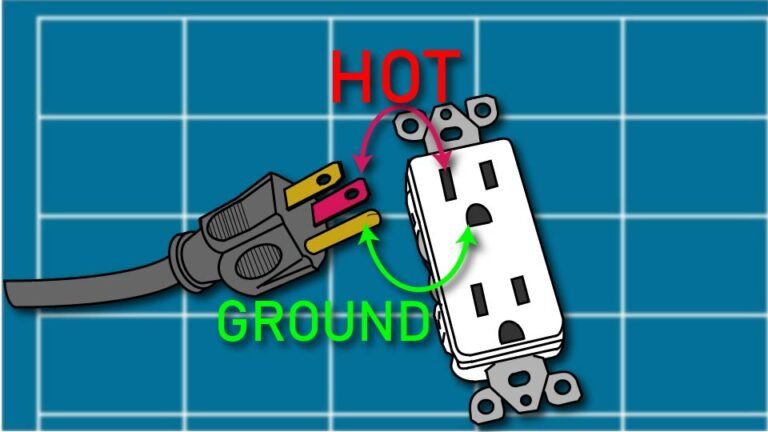
Technical line drawing of an electrical outlet and grounded-plug with the hot and ground pins identified against a blueprint-style background by John D. Reinhart, created using the Three Point Line illustration method

In standard US residential wiring, black or red wires are typically hot (the wire carrying current from the breaker panel toward whatever you’re powering), white wires are typically neutral (the wire that carries current back to the panel to complete the circuit), and bare copper or green wires are ground (the wire that gives electricity a safe path to the earth if something goes wrong, instead of through you).

“Typically” is doing real work in that sentence. Wire color is a strong convention, not a law of physics, and older homes or previous owners’ DIY work can break the pattern. Color tells you what to expect. Live-dead-live testing tells you what’s true. Trust the second one.

🔧 Wire Nuts and Connections Done Right

A wire nut (the small plastic cap that twists onto bare wire ends to join them and cap off the exposed metal) needs bare wire twisted together tightly enough that the nut grips and covers every strand — no copper visible once it’s on. If you can wiggle a wire nut off with light pressure, it’s not seated. Give it another twist.

Match wire nut size to the wire gauge and count you’re joining — too small and it won’t seat; too large and the connection can work loose over time. The color-coded sizing on the packaging isn’t decoration; it’s the manufacturer telling you which nut goes with which combination of wires.

🚫 When to Call an Electrician

Swapping an outlet, replacing a switch, adding a light fixture on an existing circuit — all reasonable weekend projects once you’ve got the live-dead-live habit. Anything involving your breaker panel itself, aluminum wiring, knob-and-tube wiring (an old wiring method, mostly phased out by the 1950s, that used ceramic knobs and tubes instead of modern insulation), or a circuit that keeps tripping for no obvious reason — that’s a phone call, not a project. There’s no shame in it. Ron’s dad called an electrician exactly once in thirty years, and it was for the panel. Everything else, Ron figured out with the right tools and enough patience.

🛒 Gear Worth Having

Klein Tools NCVT-3 Non-Contact Voltage Tester — Detects live current through the wire’s insulation without touching bare metal, and the two-point detection at the tip means you’re less likely to get a false reading. This is the tool that makes step one of live-dead-live actually reliable.

IDEAL 30-076 Wing-Nut Wire Connector Assortment — A mixed box covering the wire gauge and count combinations you’ll actually run into in a house this age, so you’re not mid-project realizing you have the wrong size nut for a three-wire joint.

Klein Tools 32717MAG Multi-Bit Insulated Screwdriver — Insulated to 1,000 volts, which matters less for the amperage in a home circuit and more because it’s one less thing to think about while your hands are near a junction box.

As an Amazon affiliate, I earn from qualifying purchases. Thank you for supporting SkippityWhistles.

📖 Related Reads


SkippityWhistles is part of the John D Reinhart content family. Writer, illustrator, videographer, and accidental filmmaker — find the whole story at JohnDReinhart.com.

9010

©2026 John D Reinhart/SkippityWhistles.com — All rights reserved

When to Replace an Extension Cord (And What Those Numbers on the Label Mean)

A damaged extension cord is a fire hazard that most people keep using anyway. Here’s how to tell when a cord is done, what the numbers on the label actually mean, and what to replace it with.

Ron Screwstrip has an extension cord in his garage that has been there since the previous owner. It is orange. It has a crack in the insulation near the plug end that he has been meaning to look at for about two years. The crack is not getting smaller.

Extension cords are one of those household items that live in a drawer or a pile until they’re needed, get used without inspection, and get put back the same way. Most of the time nothing happens. Occasionally something does, and “occasionally” is not a reassuring statistic when the thing that happens involves electricity and a fire.

Here’s how to tell when a cord is done, what the numbers on the label actually mean, and what to buy when the old one finally goes in the trash where it belongs.

🔍 The Seven Signs a Cord Needs to Go

Cracked, cut, or frayed insulation anywhere along the cord — especially near the plugs, where cords bend most often. The insulation is what stands between the live wire inside and everything around it. A crack is not a cosmetic issue. It’s a reason to stop using the cord today.

Exposed wire. If bare copper is visible anywhere, the cord is done. Full stop. Don’t tape it. Don’t wrap it in electrical tape and consider the problem solved. Electrical tape is not a repair; it’s a delay. Replace the cord.

Bent, corroded, or missing prongs on the plug. The prongs make the electrical connection. A bent prong makes a poor connection, which generates heat at the connection point. Heat at a connection point is how cords start fires.

The cord feels warm or hot during normal use. Extension cords should be at room temperature while in use. A cord that’s warm to the touch is carrying more current than it’s rated for, or has internal damage that’s increasing resistance. A hot cord is an urgent problem.

Sparking or buzzing when you plug something in. These are signs of a failing internal connection. Unplug everything, set the cord aside, and replace it.

A plug that fits loosely in the outlet or in the device. A loose connection generates heat. See above.

Age without inspection. Extension cords don’t last forever even without visible damage. If a cord has been in the garage for a decade without anyone looking closely at it, it has earned a close look. If it passes inspection, fine. If it doesn’t, now you know.

📊 What the Numbers on the Label Actually Mean

Extension cord labels have numbers on them that most people ignore entirely. The two that matter are the gauge and the amperage rating.

The gauge — usually written as something like 12/3 or 16/3 — describes the thickness of the wire inside the cord. This is counterintuitive: a lower gauge number means a thicker wire. A 12-gauge cord has thicker wire than a 16-gauge cord, which means it can carry more current over a longer distance without overheating.

For outdoor use and power tools — drills, saws, lawnmowers, anything with a motor — you want a 12-gauge cord. For indoor use with lamps, phone chargers, and small appliances, a 14 or 16-gauge cord is fine. Using a thin cord with a high-draw tool is how cords overheat, and overheating is how fires start.

The amperage rating tells you the maximum current the cord can safely carry. Most household circuits run on 15 amps. Your extension cord should be rated for at least as much as the device you’re plugging into it. If you’re running a circular saw that draws 12 amps through a cord rated for 10 amps, you’re asking for trouble.

The UL or ETL certification label on the cord means an independent testing organization has verified that the cord meets established safety standards. Buy cords with one of these certifications. It’s not a guarantee of immortality, but it means someone other than the manufacturer checked the cord’s safety claims.

🚫 The Things That Shorten a Cord’s Life Fast

Running a cord under a rug or carpet. Cords generate a small amount of heat in normal use. Under a rug, that heat has nowhere to go. Over time this degrades the insulation and can ignite the rug. Cords are not meant to be hidden — route them along baseboards if you need to manage them, but never under floor coverings.

Daisy-chaining — plugging one extension cord into another. Each cord adds resistance. More resistance means more heat. Two extension cords plugged together are carrying the load of the second cord through the first cord’s entire length, which means the first cord is working harder than it was designed to. If you need more length, buy one longer cord.

Coiling a cord tightly while it’s in use. A tightly coiled cord under load acts like a coil of wire in an electrical circuit, which is exactly what it is — and coils build up heat. Unroll the cord fully before use. Leaving it coiled is fine for storage; it’s not fine when the cord is carrying current.

Yanking a cord out of the outlet by the cord instead of the plug. This stresses the connection between the wire and the plug, which is where most cord failures begin. Pull the plug, not the cord. Every time.

🛒 Gear Worth Having

Iron Forge Cable 25ft Outdoor Extension Cord — 12/3 SJTW, 15 Amp, UL Certified — 12-gauge wire handles serious tool loads: circular saws, drills, lawnmowers, power washers. Stays flexible in cold weather so it doesn’t crack when you uncoil it on a winter morning. Lighted end confirms the cord is live. UL certified. Veteran-owned American business. This is the cord for the garage and the yard.

Belkin 12-Outlet Power Strip Surge Protector — 8ft Cord, 4,320 Joules — For the home office, entertainment center, or workshop bench where multiple devices need a single managed source. Surge protection at 4,320 joules guards against voltage spikes that can damage electronics. Rotating plug fits in tight wall outlet configurations. The right indoor solution when a single outlet isn’t enough.

Maximm Cable Flat Extension Cord — 6ft, 16 AWG, UL Listed — For furniture, behind appliances, and anywhere a standard round cord creates a bump under a rug or won’t fit behind a cabinet. The flat profile slides neatly along baseboards and behind furniture without creating a tripping hazard or a lump under flooring. 16-gauge for lamps and small appliances; not for high-draw tools.

As an Amazon affiliate, I earn from qualifying purchases. Thank you for supporting SkippityWhistles.

📖 Related Reads

How to Use Wire Nuts

GFCI Outlets: What They Are and Why They Matter

The DIYer’s Toolbox

Ron Screwstrip threw out the orange cord. He replaced it with a 12-gauge outdoor cord that lives on a reel in the garage and a surge-protected strip on the workbench. The crack near the plug is not his problem anymore. He feels significantly better about the whole situation, and slightly embarrassed it took two years.


SkippityWhistles is part of the John D Reinhart content family. Writer, illustrator, videographer, and accidental filmmaker — find the whole story at JohnDReinhart.com.

4004

©2026 John D Reinhart/SkippityWhistles.com – all rights reserved

How to Strip a Wire Safely and Correctly

Stripping a wire means removing a section of the insulating plastic cover to expose the electrical conductor underneath. Here’s how to do it.

Ron lined up a wire clearly marked 12-gauge with the 12-gauge notch on his strippers, and the wire flatly refused to fit. He tried the 10-gauge slot instead, which was obviously too big and did nothing useful. For a solid minute, Ron was ready to declare the tool mislabeled, defective, or possibly both. It was neither. The gauge stamped on the wire refers to the bare copper hiding inside — the notch was never going to accept the wire with its insulation jacket still on, and that’s not a flaw, that’s just what stripping a wire actually means.

Stripping a wire — removing a section of insulation to expose the bare conductor underneath — is one of the most basic skills in home electrical work, and also one where a little bit of understanding prevents a surprising number of “wait, why won’t this fit” moments.

🦺 Power Off, Every Single Time

Before any wire gets anywhere near a stripper, turn off the breaker for that circuit, then confirm with a non-contact voltage tester (a tool that detects live current without needing direct contact with the wire) rather than trusting the breaker label alone.

This step never gets skipped, not for a wire that looks disconnected, not for one you’re “pretty sure” is dead. Confirm it every time.

📏 The Gauge Mismatch Ron Didn’t See Coming

Wire gauge is the number describing the thickness of the copper conductor — lower numbers mean thicker wire. It is measured on the bare copper, not the insulated jacket surrounding it. A stripper’s gauge notches are sized for that bare copper too, which means the insulated wire genuinely will not slide into its matching slot — it’s supposed to look like it doesn’t fit.

Of course the wire won’t fit in the slot, Ron. That’s the whole point of the wire stripper. It will cut through the insulation, no matter how thick, but won’t nick the copper underneath.

✂️ Stripping Solid vs. Stranded Wire

Solid wire has a single, unbroken copper core and is standard in most household wiring — straightforward to strip, since there’s only one strand to protect from nicks.

Stranded wire is made of many thin copper strands bundled together, common in cords and fixtures, and needs gentler pressure from the wire stripper since they can shear off individual strands if squeezed too hard.

After stripping stranded wire, twisting the exposed strands together keeps them neat and prevents stray ones from wandering outside a connection.

📐 How Much Insulation to Remove

Outlets and switches: about 1/2 inch is standard

Wire nuts: about 3/4 inch. Stripping too little leaves too little bare copper for a solid connection. Stripping too much leaves exposed copper sitting outside the connector once everything’s assembled, which is a real safety issue, not just an untidy one.

🔍 Reading a Good Strip vs. a Bad One

A properly stripped wire shows bright, clean copper with no nicks, gouges, or thinned spots, and for stranded wire, no loose or cut strands sticking out.

Any of those signs means cutting the damaged section off and stripping again — a nicked or weakened wire is a genuine point of failure, not a cosmetic flaw to live with.

🚫 The Mistakes Worth Avoiding

  • Using a utility knife instead of proper strippers is how copper gets nicked or partially sliced through.
  • Stripping too much insulation leaves bare wire exposed outside a connector.
  • A dull or damaged stripper crushes and weakens wire instead of cleanly cutting the jacket.
  • And guessing the gauge instead of checking it, printed right on the jacket, is exactly how Ron ended up fighting the wrong notch in the first place.

🛒 Gear Worth Having

Self-Adjusting Automatic Wire Strippers — Senses the gauge automatically and strips in one squeeze, which sidesteps the whole notch-matching guesswork entirely.

Gauge-Marked Manual Wire Strippers — Clear gauge labeling and built-in cutters, for anyone who prefers manual control over an automatic tool.

Klein Tools NCVT-3 Non-Contact Voltage Tester — Confirms a wire is actually dead before anything gets stripped, cut, or connected — the step that never gets skipped.

As an Amazon affiliate, I earn from qualifying purchases. Thank you for supporting SkippityWhistles.

📖 Related Reads


SkippityWhistles is part of the John D Reinhart content family. Writer, illustrator, videographer, and accidental filmmaker — find the whole story at JohnDReinhart.com.

9007

©2026 John D Reinhart/SkippityWhistles.com — All rights reserved

How to Use Wire Nuts (And Why the Size Actually Matters)

Wire nuts are the smallest, most important connector in residential wiring. Here’s what they actually do, how to install them correctly, and the one mistake that makes them fail.

Ron Screwstrip once connected two wires with a wire nut that was too small, gave it a firm tug to confirm it held, declared victory, and closed up the junction box. The connection failed six weeks later at eleven o’clock on a Sunday night – the sparks made a glorious sight.

Wire nuts are the smallest, least glamorous connector in residential electrical work — and one of the most important. A correct wire nut connection is invisible, reliable, and lasts for decades. An incorrect one is a loose connection looking for a moment to express itself.

Here’s what they actually do, how to install them correctly, and the one thing that makes the difference between a connection that holds and one that doesn’t.

⚡ What a Wire Nut Actually Does

A wire nut is a plastic cone with a metal spring coiled inside. When you twist it clockwise onto two or more stripped wire ends, the spring compresses around the bare copper and cinches the wires firmly together. The plastic shell insulates the connection so no bare metal is exposed.

That’s the whole mechanism. No solder. No adhesive. Just a spring gripping copper under tension. When installed correctly, the connection is as reliable as anything in your walls. When installed incorrectly — wrong size, too few twists, wires not stripped to the same length — the spring doesn’t grip properly and the connection is a problem waiting to happen.

Wire nuts are standard in residential electrical work everywhere: light fixtures (including that broken ceramic ceiling fixture), switches, outlets, and anywhere wires need to be joined inside a box. They are code-approved and have been for decades. They work — when you use the right size and install them properly.

📦 A Quick Word About the Junction Box

If you’ve heard the term “junction box” and weren’t quite sure what it referred to — you’re not alone. A junction box is simply the plastic or metal box that lives inside your walls, ceiling, or wherever two or more wires meet. It protects the wire connections from the surrounding material and gives you a safe, contained place to work.

When you take down a ceiling fixture, you’ll see the junction box up in the ceiling — it’s what the fixture was mounted to. The wires coming out of it are the ones you’ll be connecting with wire nuts. Every wire connection in your house lives inside one of these boxes. They’re required by code, and they’re your workspace.

🔴 Safety First: Power Off and Verified

Before you touch any electrical wires, go to your electrical panel — the metal box, usually in a utility room, garage, or hallway, with rows of switches called breakers — and flip the breaker that controls the room or fixture you’re working on. If you’re not sure which breaker is the right one, flip on the light switch for the fixture and flip breakers one at a time until the light goes out.

Once the breaker is off, confirm the power is actually off using a non-contact voltage tester. This is a small pen-shaped tool that beeps and lights up when it detects electricity nearby — you just hold it close to the wires without touching them. Green light means the tester is working; red light and a beep means electricity is present and you need to find the correct breaker.

This step is not optional. A non-contact voltage tester costs less than fifteen dollars and the alternative is a conversation you don’t want to have. If you don’t own one, pick one up before you open anything up.

📏 The Size Question — This Is the Important Part

Wire nuts come in different sizes, and each size is designed for a specific range of wire thicknesses and a specific number of wires. The packaging always says what wire gauges the nut is rated for — look for that before you buy.

The color coding on wire nuts changes by manufacturer, which is genuinely unhelpful, but the colors are a rough guide: orange nuts are for smaller, thinner wires; yellow nuts handle the standard household wiring gauge (14 AWG) that you’ll find in most lighting circuits; red nuts handle the slightly heavier gauge (12 AWG) used on outlets and kitchen circuits. If you’re not certain which you have, an assortment kit removes the guesswork entirely — you have every size on hand and you pick the right one for the job.

The right wire nut feels snug when you begin threading it on, grips with increasing resistance as you twist, and sits firmly when fully seated. If it spins freely and never tightens, it’s too large. If it won’t start threading at all, it’s too small. Try the next size.

🧵 A Quick Word About Wire Types

The wires in your walls are almost certainly solid wire — a single thick copper conductor wrapped in colored plastic insulation. Solid wire is what wire nuts were designed for, and it’s what you’ll encounter in virtually every ceiling fixture, switch, and outlet in a residential home.

Stranded wire — which looks like a bundle of thin copper threads inside the insulation rather than one solid piece — shows up in lamp cords, extension cords, and appliances. Wire nuts can be used with stranded wire, but the nut needs to be specifically rated for it. For a ceiling fixture replacement, you’re almost certainly working with solid wire.

🔧 How to Install a Wire Nut Correctly

Start by stripping about half an inch to three-quarters of an inch of the colored plastic insulation off the end of each wire you’re connecting. Use wire strippers for this — they have numbered slots that match wire gauges so you get a clean strip without nicking the copper underneath. The exposed copper should be shiny and undamaged. Strip each wire to the same length so the copper ends line up evenly when you hold them together.

Hold the stripped wire ends alongside each other so the copper tips are even. Now, which wire connects to which? In a standard ceiling fixture, the color tells you everything you need to know: the black wire (called the “hot” wire, the one carrying current) connects to the black wire from the fixture. The white wire (called the “neutral”) connects to the white wire from the fixture. The bare copper wire, or green wire, is the ground — it connects to the ground wire from the fixture. Same color to same color, every time.

If you’re working in a junction box where multiple wires come together — for instance, a box that feeds more than one fixture — all wires of the same color connect together under one nut. Three black wires all get twisted together under one wire nut. Three white wires under another. The ground wires under a third. It looks like more wires than you expected, but the principle is the same: same color, same nut.

Before putting the nut on, give the wires a gentle clockwise pre-twist using needle-nose pliers. This isn’t required, but it gives the spring inside the nut more to grip and produces a tighter, more reliable connection — especially worth doing if you’re new to this.

Place the wire nut over the exposed copper ends and twist it clockwise with firm, steady pressure. You’ll feel resistance build as the spring engages. Keep twisting until the nut is snug, no bare copper is visible below the bottom edge of the nut, and the nut doesn’t wobble when you wiggle it.

Now test it: grip each wire individually and give it a firm tug. A correctly installed wire nut does not release any wire. If a wire pulls free, unscrew the nut, check that the wires are stripped evenly and aligned properly, and do it again. Wire nuts cost almost nothing. A connection that fails inside a closed ceiling costs significantly more.

One optional finishing touch: wrap a single layer of electrical tape around the base of the nut and the wires just below it. This isn’t required by code, but it adds peace of mind — particularly when you’re folding the wires back into a ceiling box and pushing the fixture up against it.

🚫 The Mistakes That Make Connections Fail

Wrong size nut is the most common problem. Too large and the spring can’t grip the wires; too small and it won’t thread on properly. Match the nut to the wire gauge listed on the package.

Uneven strip lengths cause one wire to be gripped firmly and the other barely at all. The shorter wire is the one that pulls free during the tug test. Strip them to the same length before you start.

Leaving bare copper visible below the nut after installation means the strip was too long or the nut is too small. Trim the wires slightly or move up a size.

Reusing cracked or old wire nuts is never worth it. Wire nuts are inexpensive. A fresh nut on every connection is the right call.

🛒 Gear Worth Having

Secmity 122-Piece Wire Connector Assortment Kit — 5 Sizes, Color-Coded — Five sizes covering the full range of residential wire gauges, organized in a labeled storage box. This is the kit that ends the size guessing game permanently. Buy it once, have the right nut for every job.

Klein Tools NCVT1P Non-Contact Voltage Tester — The tool you hold near the wires before you touch anything. Green light means it’s working; red light and a beep means the power is still on and you need to find the right breaker. Klein has been making professional electrical tools for over 160 years. This one costs less than fifteen dollars and earns its place in every toolbox.

WAGO 221 Lever-Nut Assortment Kit (78-Piece, with Case) — The modern alternative to twist wire nuts. Flip the orange lever up, insert the stripped wire, push the lever down. No twisting required, works with both solid and stranded wire, and fully reusable — flip the lever back up and the wire pulls free cleanly. Professional electricians reach for these. Worth knowing they exist.

VCELINK Automatic Wire Stripper and Cutter — Self-Adjusting, 28-10 AWG — The self-adjusting jaw finds the right strip depth on its own, so you get a clean, even strip every time without nicking the copper. Even strip lengths are the foundation of a wire nut connection that actually holds.

As an Amazon affiliate, I earn from qualifying purchases. Thank you for supporting SkippityWhistles.

📖 Related Reads

Ron Screwstrip now owns an assortment kit, a voltage tester, and a firm policy about the tug test. The ceiling fixture went up on a Saturday afternoon and has been working quietly ever since. He doesn’t think about it anymore. That’s exactly how it’s supposed to go.


SkippityWhistles is part of the John D Reinhart content family. Writer, illustrator, videographer, and accidental filmmaker — find the whole story at JohnDReinhart.com.

9008

©2026 John D Reinhart/SkippityWhistles.com – all rights reserved